


针对矿山+0 m中段以上大倍线充填,开展了充填料浆管道输送水力学计算,确定了不同料浆状态下的临界流速和管道输送沿程阻力;对比分析了不同的充填料浆管道输送系统布置方案,并结合充填料浆管道输送水力学计算结果,确定了最佳的管道输送方案;根据矿山生产实际情况,确定了充填工艺参数;同时,结合充填尾砂基本性能、充填工艺参数及充填料浆管道输送沿程阻力损失,确定了充填加压泵类型及工况参数。最终通过现场实际应用,取得了较为理想的充填效果。
1 充填材料基本性质
表1 尾砂化学成分分析
Table 1
| 成分 | 质量分数 | 成分 | 质量分数 |
|---|---|---|---|
| SiO2 | 58.4 | P2O5 | 0.141 |
| Fe2O3 | 6.02 | TiO2 | 0.822 |
| Al2O3 | 18.5 | CuO | 0.0027 |
| CaO | 3.25 | As2O3 | 0.111 |
| MgO | 2.34 | SO3 | 0.329 |
| Na2O | 3.27 | Au | 0.52 |
| K2O | 3.04 | Ag | 3.21 |
表2 分级尾砂粒级组成
| 目数 | 粒径/μm | 分计/% | 累计/% |
|---|---|---|---|
| +40 | +425 | 24.88 | 24.88 |
| -40~+60 | -425~+250 | 12.16 | 37.04 |
| -60~+80 | -250~+180 | 11.29 | 48.33 |
| -80~+100 | -180~+150 | 21.36 | 69.69 |
| -100~+140 | -150~+106 | 9.97 | 79.66 |
| -140~+200 | -106~+74 | 5.98 | 85.64 |
| -200~+400 | -74~+37 | 8.74 | 94.38 |
| -400 | -37 | 5.62 | 100.00 |
分级尾砂物理性质测试结果显示,分级尾砂比重为2.74,松散容重为1.45 t/m3,松散尾砂孔隙率为47.1%,属于正常尾砂范畴,与一般充填尾砂无较大区别,可作为充填骨料使用。
2 充填料浆管道输送水力学计算
2.1 临界流速
杜兰德公式[15]如下:
式中:
式中:
充填料浆密度在1.61~1.79 g/cm3之间,计算不同管径及充填料浆浓度下的临界流速,结果如表3所示。
由表3可知:在输送管径相同的条件下,临界流速随着料浆质量浓度的增加而减小;在输送料浆质量浓度相同的条件下,临界流速随着管径的增加而增大,说明临界流速与管径成正比,而与料浆质量浓度成反比。采用杜兰德公式计算时,将料浆中细粒级颗粒作为输送载体,类似于均质流,因此,输送料浆质量浓度越高则颗粒沉降越慢,料浆输送要求达到的临界流速越低;当料浆浓度超过临界浓度后,料浆管道输送不再要求达到最低输送流速(临界流速)。
表3 临界流速计算结果
Table 3
| 管径D/m | 不同料浆质量浓度下的临界流速 | |||
|---|---|---|---|---|
| 66% | 68% | 70% | 72% | |
| 0.080 | 1.10 | 1.09 | 1.07 | 1.06 |
| 0.100 | 1.23 | 1.22 | 1.20 | 1.18 |
| 0.125 | 1.38 | 1.36 | 1.34 | 1.32 |
| 0.150 | 1.51 | 1.49 | 1.47 | 1.45 |
管道输送工作流速应比临界流速大30%~50%。根据计算的临界流速,按照比临界流速大50%计算出不同管径和不同料浆浓度下的实际工作流速,结果如表4所示。
表4 实际工作流速计算结果
| 管径D/m | 不同料浆质量浓度下的临界流速/(m | |||
|---|---|---|---|---|
| 66% | 68% | 70% | 72% | |
| 0.080 | 1.65 | 1.64 | 1.61 | 1.59 |
| 0.100 | 1.85 | 1.83 | 1.80 | 1.77 |
| 0.125 | 2.07 | 2.04 | 2.01 | 1.98 |
| 0.150 | 2.27 | 2.24 | 2.21 | 2.18 |
2.2 管道沿程阻力损失
式中:
计算沿程阻力损失时一般需要体积浓度,体积浓度与重量浓度之间存在以下关系:
式中:
由于矿山充填系统已建成,其充填浓度为66%~68%,井下充填管径为DN100,按照此参数,采用费祥俊公式计算充填料浆沿程阻力损失结果如表5所示。
表5 0.1 m管径下沿程阻力损失计算结果
Table 5
| 充填浓度/% | 工作流速 /(m·s-1) | 充填流量 /(m3·h-1) | 沿程阻力损失(mH2O/m) | 沿程阻力损失/(Pa·m-1) |
|---|---|---|---|---|
| 66 | 1.85 | 59.06 | 0.1407 | 1 379.82 |
| 68 | 1.83 | 60.48 | 0.1522 | 1 492.59 |
| 70 | 1.80 | 61.89 | 0.1744 | 1 710.31 |
| 72 | 1.77 | 63.59 | 0.1991 | 1 952.53 |
3 充填料浆管道输送系统方案
3.1 118 m斜井充填料浆管道输送方案(方案一)
(1)充填管路布置。充填站充填管道经118 m副斜井与井下各中段相连通,充填管路先进入100 m中段,在100 m中段沿运输主巷进行主管道的铺设,以各穿脉为分支管道铺设从而进入充填采场。75 m中段及50 m中段的管路铺设,从118斜井与75 m中段、50 m中段相连通处进入中段运输主巷道,沿运输主巷进行主管道的铺设,以各穿脉为分支管道铺设从而进入充填采场。方案一充填管路布置如图1所示。
图1
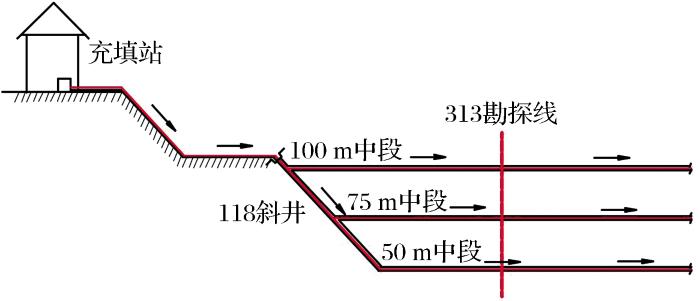
图1
118 m斜井充填料浆管道输送方案
Fig.1
Transportation plan of filling slurry pipeline in 118 m inclined well
(2)几何充填倍线。根据118 m斜井充填料浆管道输送方案(方案一),计算不同中段几何充填倍线,结果如表6所示。
表6 方案一各中段几何充填倍线计算结果
Table 6
| 中段/m | 高差/m | 勘探线 | 总长/m | 几何倍线 |
|---|---|---|---|---|
| 100 | 41 | 315 | 1 036 | 25.3 |
| 100 | 41 | 317 | 1 096 | 26.7 |
| 100 | 41 | 319 | 1 183 | 28.9 |
| 100 | 41 | 2 | 1 302 | 31.8 |
| 100 | 41 | 4 | 1 357 | 33.1 |
| 100 | 41 | 8 | 1 468 | 35.8 |
| 100 | 41 | 12 | 1 617 | 39.4 |
| 100 | 41 | 16 | 1 728 | 42.1 |
| 75 | 66 | 315 | 1 133 | 17.2 |
| 75 | 66 | 317 | 1 183 | 17.9 |
| 75 | 66 | 319 | 1 256 | 19.0 |
| 75 | 66 | 2 | 1 573 | 23.8 |
| 75 | 66 | 4 | 1 623 | 24.6 |
| 75 | 66 | 8 | 1 732 | 26.2 |
| 75 | 66 | 12 | 1 854 | 28.1 |
| 75 | 66 | 16 | 1 956 | 29.6 |
| 50 | 91 | 315 | 1 058 | 11.6 |
| 50 | 91 | 317 | 1 138 | 12.5 |
| 50 | 91 | 319 | 1 197 | 13.1 |
| 50 | 91 | 323 | 1 305 | 14.3 |
| 50 | 91 | 327 | 1 406 | 15.5 |
| 50 | 91 | 2 | 1 577 | 17.3 |
| 50 | 91 | 4 | 1 668 | 18.3 |
3.2 120 m平硐充填料浆管道输送方案(方案二)
(1)充填管路布置。充填站充填管路经地表铺设至120 m平硐,在120 m平硐主运输巷进行主管道铺设。对于100~120 m中段空区充填,以各穿脉为分支管道铺设。另外,从120 m中段313线附近掘进一穿脉与313斜井相贯通(贯通距离约为30 m),从而将充填管路通过313斜井下放至100 m中段,并以各穿脉为分支管道铺设从而进入75~100 m中段空区进行充填。经过313线斜井将充填管铺设至75 m中段和50 m中段,并以各中段穿脉为分支管道铺设从而进入空区进行充填,方案二充填管路布置如图2所示。
图2
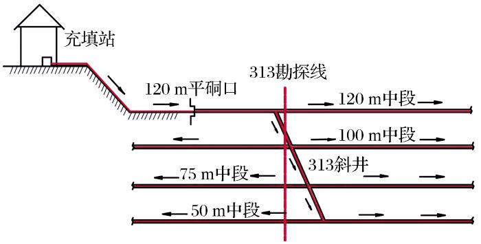
图2
120 m平硐充填料浆管道输送方案
Fig.2
Transportation plan of filling slurry pipeline in 120 m adit
(2)几何充填倍线。根据120 m平硐充填料浆管道输送方案(方案二),计算不同中段几何充填倍线,结果如表7所示。
表7 方案二各中段几何充填倍线计算结果
Table 7
| 中段 | 高差/m | 勘探线 | 总长/m | 几何倍线 |
|---|---|---|---|---|
| 120 | 21 | 307 | 599 | 28.5 |
| 120 | 21 | 311 | 761 | 36.2 |
| 120 | 21 | 315 | 862 | 41.4 |
| 120 | 21 | 319 | 969 | 46.1 |
| 120 | 21 | 4 | 1 123 | 53.3 |
| 120 | 21 | 8 | 1 225 | 58.3 |
| 120 | 21 | 12 | 1 347 | 64.1 |
| 120 | 21 | 16 | 1 459 | 69.5 |
| 100 | 41 | 315 | 953 | 23.2 |
| 100 | 41 | 317 | 1 003 | 24.5 |
| 100 | 41 | 319 | 1 060 | 25.9 |
| 100 | 41 | 2 | 1 153 | 28.1 |
| 100 | 41 | 4 | 1 214 | 29.6 |
| 100 | 41 | 8 | 1 315 | 32.1 |
| 100 | 41 | 12 | 1 438 | 35.1 |
| 100 | 41 | 16 | 1 551 | 37.8 |
| 75 | 66 | 315 | 1 034 | 15.7 |
| 75 | 66 | 317 | 1 084 | 16.4 |
| 75 | 66 | 319 | 1 157 | 17.5 |
| 75 | 66 | 2 | 1 466 | 22.2 |
| 75 | 66 | 4 | 1 517 | 22.9 |
| 75 | 66 | 8 | 1 627 | 24.7 |
| 75 | 66 | 12 | 1 749 | 26.5 |
| 75 | 66 | 16 | 1 852 | 28.1 |
| 50 | 91 | 315 | 1 118 | 12.2 |
| 50 | 91 | 317 | 1 198 | 13.2 |
| 50 | 91 | 319 | 1 257 | 13.8 |
| 50 | 91 | 323 | 1 366 | 15.0 |
| 50 | 91 | 327 | 1 468 | 16.0 |
| 50 | 91 | 2 | 1 639 | 18.0 |
| 50 | 91 | 4 | 1 731 | 19.0 |
3.3 充填料浆管道输送方案选择
选用方案一时,100 m中段最长充填管路为1 728 m,几何充填倍线为42.1,输送阻力为2.84 MPa(浓度为68%,管径为100 mm);75 m中段最长充填管路为1 956 m,几何充填倍线为29.6,输送阻力为2.88 MPa;50 m中段最长充填管路为1 668 m,几何充填倍线为18.3,水头总损失为1.86 MPa。
采用方案二时,100 m中段最长充填管路为1 551 m,几何充填倍线为37.8,输送阻力为2.48 MPa(浓度为68%,管径为100 mm);75 m中段最长充填管路为1 852 m,几何充填倍线为28.1,输送阻力为2.67 MPa;50 m中段最长充填管路为1 731 m,几何充填倍线为19,输送阻力为1.99 MPa。
通过对比分析方案一与方案二可知,在100 m中段和75 m中段,方案一的充填管路长度、几何充填倍线和沿程管路输送阻力均大于方案二,从而导致方案一充填料浆的输送难度较方案二大,且投资费用也更多。而在50 m中段,上述3个参数相差不大。同时,与方案一相比,方案二在充填覆盖范围方面多增加了120 m中段,从而能够回收更多残矿并创造更大的经济效益。
综上所述,选定120 m平硐充填料浆管道输送方案(方案二)作为0 m以上加压充填井下充填管路铺设方案。
4 充填参数确定及加压泵选择
4.1 充填参数
根据充填料浆管道输送水力学计算结果,结合充填系统及生产现状,确定0 m中段以上加压充填工艺参数如下:
(1)充填管径:结合现有充填系统,考虑加压输送管道管径与原有系统相配套,从而对0 m中段以下各中段扩大充填范围,因此,选定充填管径为100 mm。
(2)输送浓度:采用现有系统充填浓度,即充填浓度在66%~68%之间。
(3)工作流速:根据计算的临界流速,在充填管径为100 mm、充填浓度为66%~68%时,工作流速应保证在1.85~2.00 m/s之间。
(4)充填流量:根据选取的管径、工作流速和充填浓度计算出充填流量为60 m3/h。
4.2 充填加压泵选择
5 应用效果
某金矿山加压充填系统于2014年建成运行,期间各项运行指标均达到设计要求,运行状况良好。据统计,截至目前矿山0 m中段至120 m充填采空区体积为13.96
6 结论
针对矿山0 m中段以上大倍线充填,开展了充填料浆管道输送水力学计算,确定了最佳的充填工艺参数;对比分析了不同的充填料浆管道输送系统布置方案,选取了最佳的管道输送方案;最终综合分析确定了充填加压泵类型及工况参数。本研究获得以下主要结论:
(1)通过开展充填料浆管道输送水力学计算,确定了不同料浆状态下的输送临界流速,并以此为基础,结合充填管道参数,推荐最佳的充填料浆管道输送工作流速;
(2)依据推荐的工作流速,结合充填料浆参数及管道参数,计算了不同充填料浆状态下的管道沿程阻力损失,为充填加压泵选择提供了依据;
(3)对比分析了不同充填料浆管道输送布置方案,最终选用120 m平硐充填料浆管道输送方案(方案二),其最长充填管路为1 551 m,几何充填倍线为37.8,最大输送管道阻力为2.48 MPa(浓度为68%,管径为100 mm时);
(4)根据充填料浆管道输送水力学计算结果,结合充填系统及生产现状,确定0 m中段以上加压充填工艺参数:充填管径为100 mm;输送浓度在66%~68%之间;工作流速在1.85~2.00 m/s之间;充填流量为60 m3/h;
(5)根据尾砂性能,结合充填工艺参数,推荐采用柱塞式充填加压泵,其相关技术参数:泵出口压力为5 MPa;泵流量为60 m3/h;
(6)矿山加压充填系统建成运行期间各项运行指标均达到设计要求,运行状况良好。同时,初步估计,0 m以上矿量的回采可增加经济效益10 124.09万元,盈利190.85元/吨。
参考文献
天马山硫金矿段高大型复杂空区群充填
[J].
Filling for high-large comples goaf masses of Tianmashan S-Au ore block
[J].5(Supp
.
金厂峪金矿充填尾砂基本性能试验研究
[J].
Experimental study on basic performance of Jinchangyu filling tailings
[J].
废石尾砂胶结充填力学研究进展
[J].
Advances in mechanics of cemented rock-tailings fill research
[J].
绿色开采的概念与技术体系
[J].
Technological system and green mining concept
[J].
金川镍矿废弃物在充填采矿中利用现状与展望
[J].
Present research situation and prospect of nickel utilization of wastes in filling mining technology in Jinchuan mine
[J].
尾砂胶结充填在某金属矿采空区处理中的应用
[J].
Application of tailing-cemented filling in goaf management of a metal mine
[J].
某矿全尾砂胶结充填物料性能研究
[J].
Study on the properties of the unclassified tailings cemented backfill materials in a mine
[J].
充填采矿技术与应用
[M].
The Technology and Application in Backfilling Mining
[M].
浆体管道输送临界流速的研究
[J].
Critical flow rate for slurry pipeline transportation
[J].
金属矿山尾矿高浓度管道输送技术研究
[D].
Technical Research in High Concentrations of Tailings Pipeline for Metal Mines
[D].
深井矿山充填理论与管道输送技术
[M].
Filling Theory and Pipeline Transportation Technology in Deep Mine
[M].
浆体管道输送临界流速的影响因素及计算分析
[J].
Effect factors and calculating analysis of critical flow velocity in slurry pipeline transportation
[J].
粗颗粒物料管道水力输送不淤临界流速计算
[J].
Non-silting critical velocity calculation of coarse-grained materials in hydraulic pipeline
[J].
浆体管道输送临界流速经验公式适宜性分析
[J].
Suitability analysis of empirical formulas for critical velocity in slurry pipeline transportation
[J].
铜尾矿流变特性与管道输送阻力计算
[J].
Study of the rheological characteristics of copper tailings and calculation of resistance in pipeline transportation
[J].
膏体管道输送阻力损失研究
[J].
Study on resistance loss in paste piping transportation
[J].
高浓度充填料浆流变特性及其管道输送阻力损失研究
[J].23(增2): 301
.
Study on the rheological characteristics of high-concentration filling mixture and its resistance loss in pipeline transportation
[J].23(Supp
.2):301
.
矿山充填料浆水力坡度计算
[J].
Hydraulic gradient calculation of mine filling paste
[J].
考虑时变性的全尾膏体管输阻力计算
[J].
Calculation of resistance in total tailings paste piping transportation based on time-varying behavior
[J].
胶结充填过程中的成本管控
[J].
Cost control in the process of cement filling
[J].
高浓度尾矿输送系统设计方法与实践
[J].
Design method and practice for transporting tailings slurry with high density
[J].
加压泵管道输送充填技术研究与实践
[J].
Research and practice of backfill technology with pipeline transportation by pressure pump
[J].
永平铜矿坑采充填加压输送系统技术探讨
[J].
Discussion on the technology of back filling pressurizing transportation system in Yongping copper mine’s underground mining operation
[J].
全粒级碎石胶结充填材料及泵送试验研究
[J].
Experimental research on full graded gravel cement filling materials and their pumping
[J].


 甘公网安备 62010202000672号