


能源消耗是制约可持续发展的一大问题。工业和矿业部门消耗的能源约占世界能源总消耗量的37%[1]。在矿山高温环境下矿井降温又是一项较大的开支。南非在矿井降温方面已走在世界前列,该国通过立法规定采矿环境温度不得高于湿球温度(27.5 ℃)[2]。我国在《煤矿安全规程》中规定,工人掘进采掘面温度不得超过干球温度(26 ℃),采掘面空气温度超过30 ℃时必须停止采掘作业[3,4]。随着矿井开采深度的不断增加(目前最大开采深度已超过3 km[5],称为超深井),初始岩石温度的升高和空气自压缩热的增加,对采矿环境的舒适情况非常不利。仅采用空气通风不足以去除深井围岩、采矿设备和爆破等产生的热量[5](中国南方夏季室外温度可达35 ℃以上)。资料显示,不同矿井的初始岩石温度在30~80 ℃之间变化[5,6],随着采掘不断深入,对矿井通风进行合理改进很有必要。
目前在矿井通风领域已经形成了几种成熟的数学模型,包括一维传热模型、一维网络流模型和以通风为重点的三维计算流体力学模型(CFD)[7,8,9],此外还有一些通风除尘模型[10,11,12,13]。一些学者通过CFD模拟研究了矿井通风的设计。Park等[14]通过设计几种不同的管道参数研究了用作储存的封闭矿井的空气质量问题。Sasmito等[5,15]创建了地下矿井热量管理的三维模型,探究了多项因素对矿井降温的影响程度,并开发了几种地下矿井通风模型,确定了辅助通风系统能够提供足够的氧气和降低掘进面的甲烷浓度。李杰林等[16]运用数值模拟方法,结合高温矿井井下环境的特点,对高温环境进行模拟,提出了使用预计热舒适指标(PMV)评价环境热舒适程度的方法。高建良等[17]和张树光等[18]借助计算机模拟对风流热环境、进气流和围岩的热交换过程以及巷道调热圈等进行了模拟计算。Kurnia等[19]研究开发了一种可以有效控制地下矿井中危险气体和粉尘的辅助通风系统。
综上可知,计算机数值模拟已经广泛应用在矿井通风降温、除尘和排污等诸多方面。辅助通风系统常被用来去除地下矿井空气中的柴油颗粒、甲烷或粉尘等有害物质,国内外学者的研究结果表明,辅助通风系统可以有效改善短距离巷道的通风条件,但这些研究通常忽略了换热因素。因此,本文基于前人研究,开展辅助通风设施对高温巷道通风降温的影响研究。旨在研究引入辅助通风设施后,如何提高短距离高温矿井的通风降温性能。通过引入成本较低的辅助通风设施,对高温矿井掘进巷道的温度环境产生较大的影响,使掘进面附近的温度保持在法定范围内,进而指导高温矿井局部巷道通风结构设计,改善高温矿山局部巷道的通风冷却效果。
1 几何模型设定
图1

图1
计算模型示意图
(a)计算模型的3D视图;(b)计算模型的顶视图
Fig.1
Schematic diagram of calculation model
2 计算模型及边界条件
2.1 软件及数值模型
几何模型创建和网格划分都是在ICEM-CFD中完成。使用ICEM设定最大网格尺寸为0.1 m,整个模型拥有约560万个四面体非结构化网格。
流体区域数值模拟在ANSYS Fluent中进行。湍流模型是地下环境流体流动行为模拟的关键部分,Fluent中有4种湍流模型,即Spalart-Allmaras、K-Epsilon、K-Omega和RSM。Kurnia等[19]通过试验验证了4种模型,最终证明
2.2 数学模型
在整个巷道中,同时存在质量变化、动量变化和能量传输过程,考虑到围岩散热以及用于冷却的冷气通风质量、动量和能量方程分别为
式中:
在关于湍动能k的方程的基础上,再引入一个关于湍动能耗散率
湍动黏度
式中:
K-Epsilon模型是考虑了求解湍流动能k和耗散速率ε的双方程模型,它与湍流黏度相结合。该模型可表示为
式中:
2.3 边界条件
《金属非金属矿山安全规程》(GB 16423-2006)中规定:运输巷道、采区进风道最高风速为6 m/s。因此,按照规程规定对没有配备辅助通风设施的情况设置了3 m/s和6 m/s的进气道空气流速,对增加辅助通风设施的情况仅设置了3 m/s的进气道空气流速[20]。所有进气温度均设置固定温度为293 K[5],所有墙壁(除辅助通风设施外)设置318 K的固定温度。假设巷道围岩均质且各向同性;巷道壁面换热条件一致,即:假定在某一条巷道的壁面,其换热条件相同,均在其周长上,热交换的条件也相同;围岩热量完全传递给风流。数值模拟使用商业有限体积求解器ANSYS Fluent求解几何和边界条件。围岩和辅助通风设施均使用Fluent中默认的“wall”设置。气流使用默认空气设置,使用1个大气压时的空气参数。湍流模型选择标准K-Epsilon模型,收敛容差设置为10-4,利用半隐式压力连接方程(SIMPLE)算法,二阶迎风离散化方法和代数多重网格法(AGM)求解方程。该研究的详细边界条件和计算模型设置如表1和表2所示。
表1 边界条件设定
Table 1
| 类型或参数 | 设定类型或参数值 | 类型或参数 | 设定类型或参数值 |
|---|---|---|---|
| 进气道入口 | 速度入口 | 通风温度/K | 293 |
| 风速/(m·s-1) | 3/6 | 巷道环境初始温度/K | 308 |
| 进气道出口 | 自由流出口 | 初始岩石温度/K | 318 |
| 其他壁面及辅助通风设施 | 墙 |
表2 计算模型设置
Table 2
| 类型或参数 | 设定类型或参数值 | 类型或参数 | 设定类型或参数值 |
|---|---|---|---|
| Solver | 基于压力法 | 操作压力/kPa | 1.013 |
| 求解格式 | 隐式 | 收敛容差 | 10-4 |
| 时间属性 | 稳态 | 最大迭代步数 | 4 000 |
| 湍流模型 | 标准K-Epsilon模型 |
3 数值模拟分析
3.1 进气速度的影响(无辅助通风)
图2
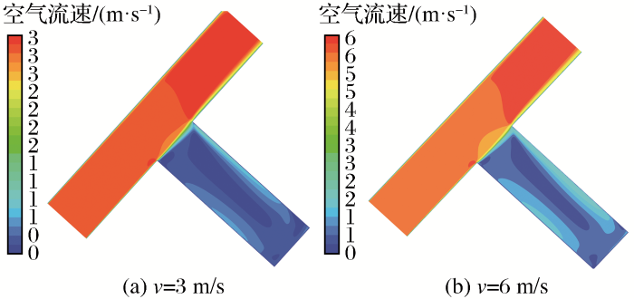
图2
空气流速随进气速度的变化(无辅助通风)
Fig. 2
Change of air flow rate with intake air speed (without auxiliary ventilation)
对上述横截面的温度分布情况(图3)进行分析。由于通过进气道的冷却气流几乎没有进入掘进巷道,掘进面附近的温度几乎没有明显降低,仅在掘进巷道与进气道连接的附近有明显的降低。当进气速度由3 m/s增加至6 m/s时,掘进面附近的温度变化可以忽略不计,仍远超《煤矿安全规程》中的规定值。由此可得,仅仅增加进气道中的空气流速不足以降低掘进巷道中的高温,因此有必要增加辅助通风设施。
图3
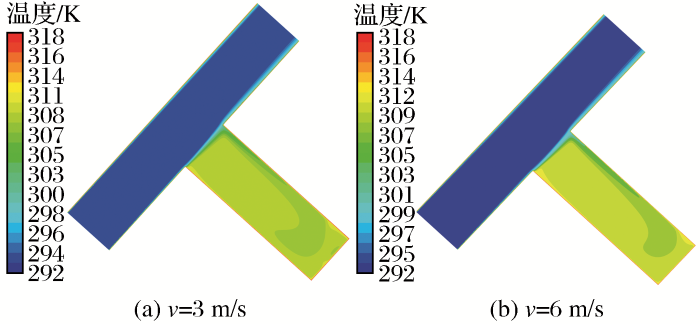
图3
温度分布随进气速度的变化(无辅助通风)
Fig.3
Change of temperature distribution with intake air speed (without auxiliary ventilation)
温度随掘进面距离的变化如图4所示。当进气速度为3 m/s时,整个掘进巷道的温度非常高,在掘进面附近高达35 ℃,远超《煤矿安全规程》规定的温度上限。当进气速度增加至6 m/s时,巷道内温度略微下降,从曲线中可以看出温度最低点高于34 ℃,仍远高于限制温度。进气速度从3 m/s增加至6 m/s时仅带来平均0.6 ℃的温度变化,因此只有改变通风设计才能进一步降低掘进面的温度。
图4
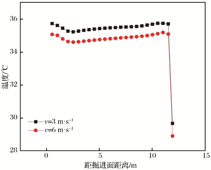
图4
平均温度随掘进面距离的变化(无辅助通风)
Fig.4
Change of average temperature with distance of tunnelling face (without auxiliary ventilation)
3.2 辅助通风设施长度的影响
图5
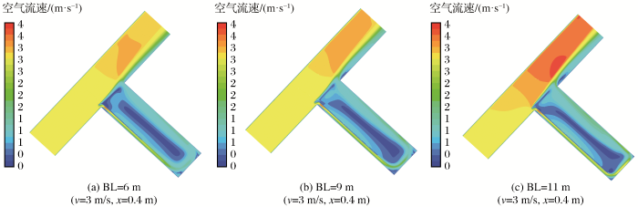
图5
空气流速随辅助通风设施长度的变化
Fig.5
Change of air flow rate with the length of auxiliary ventilation facilities
通过引入3种长度(BL=6 m、BL=9 m和BL=11 m)的辅助通风设施,得到y=1.5 m掘进巷道的温度分布情况如图6所示。在辅助通风设施的作用下,大量冷却气体经进气道由辅助通风设施引导流入到掘进巷道,巷道温度显著降低。结果显示,引入辅助通风系统后掘进巷道内的温度明显降低。
图6
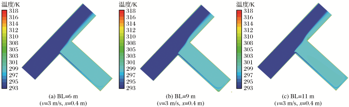
图6
温度分布随辅助通风设施长度的变化
Fig.6
Change of temperature distribution with the length of auxiliary ventilation facilities
从图7可见,在3种长度(BL=6 m、BL=9 m和BL=11 m)下,掘进面最高温度为28.2 ℃,高于规定值,但明显小于没有辅助通风设施的情况,掘进面附近和掘进巷道入口处的温度均出现快速下降。值得注意的是,随着辅助通风设施长度的增加,掘进巷道的冷却效果先变好后变差。当BL=11 m时,掘进巷道温度明显高于BL=6 m和BL=9 m的情况,测试的3种长度中BL=9 m的冷却效果最佳。
图7
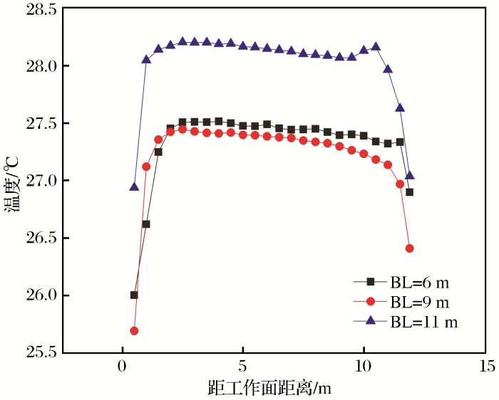
图7
平均温度随辅助通风设施长度的变化(v=3 m/s,x=0.4 m)
Fig.7
Change of average temperature with the length of auxiliary ventilation facilities (v=3 m/s,x=0.4 m)
巷道内空气的速度流线图可以清楚地展示空气的运动轨迹。从图8可以看出,BL=6 m时冷却气流由辅助通风设施引导流出后,气流沿墙壁向前方流动,在冲击掘进面之后沿另一侧墙壁流出,在整个掘进巷道形成漩涡状;BL=9 m时存在类似的流线分布规律,不同的是BL=9 m时巷道中间旋涡有更多的流线分布,整个巷道的温度发展更加均匀;对于BL=11 m,由于通风设备过于靠近掘进面,冷却气流经由辅助通风设施流出后即冲击掘进面,冷却气流紧贴掘进面流向另一侧墙壁后沿墙壁流出,冷却气流的直接流出且与掘进巷道空气接触不足,导致在3种情形下BL=11 m时的冷却效果最差。
图8
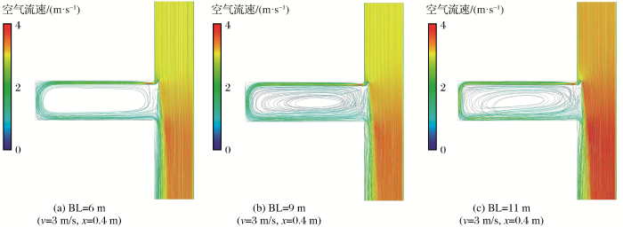
图8
速度流线随辅助通风设施长度的变化
Fig.8
Variation of velocity streamline with the length of auxiliary ventilation facilities
3.3 辅助通风设施与墙壁距离的影响
图9
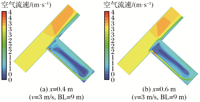
图9
空气流速随辅助通风设施与墙壁距离的变化
Fig.9
Change of air flow rate with the distance of auxiliary ventilation facilities and walls
从图10中可以看出巷道内的温度随辅助通风设施与墙壁之间距离的变化情况。与前面模拟结果类似,更多的冷却气流使掘进巷道温度降低。结果表明,随着辅助通风设施与墙壁之间距离的增加,更多冷却空气进入掘进巷道,冷量的增加最终降低了掘进巷道中的温度。
图10
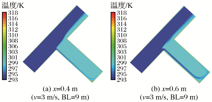
图10
温度分布随辅助通风设施与墙壁距离的变化
Fig.10
Change of temperature distribution with the distance of auxiliary ventilation facilities and walls
截面平均温度随着截面与掘进面距离变化的曲线如图11所示。由图可以看出,随着距离的增加掘进巷道获得了更低的温度,在距离掘进面1 m处出现最大为2.3 ℃的温差,整个掘进巷道平均温差为1.5 ℃,表明增加辅助通风设施与墙壁之间的距离明显改善了掘进巷道的通风降温条件。
图11
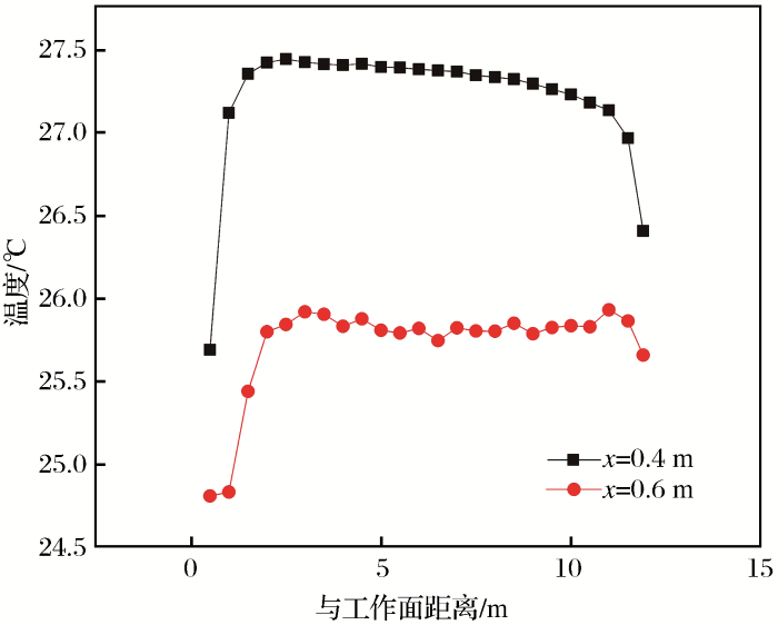
图11
平均温度随辅助通风设施与墙壁距离的变化(v=3 m/s,BL=9 m)
Fig.11
Change of average temperature with the distance of auxiliary ventilation facilities and walls
3.4 进气速度的影响(增加辅助通风设施)
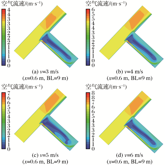
在固定辅助通风设施参数的情况下,另一种改善通风性能的方法就是增加进气道的空气流速。较高的空气流速意味着到达掘进巷道的空气流量也较高。这里模拟使用的辅助通风设施长度BL=9 m,辅助通风设施与墙壁之间的距离x=0.6 m,根据《金属非金属矿山安全规程》设置进气速度分别为3,4,5,6 m/s。
随着风速从3 m/s增加至6 m/s,到达掘进面的风量也越来越大。图12中值得注意的是,增加进气速度会减小掘进巷道中存在的低风速区域,但无法消除。
图12
风速从3 m/s增加至6 m/s,y=1.5 m掘进巷道温度分布见图13。由图可知,冷却气流由辅助通风设施引导后流出冲击掘进面后返回,随着风速的增加,低温区域逐渐增加,这意味着掘进巷道获得了良好的降温效果。
图13
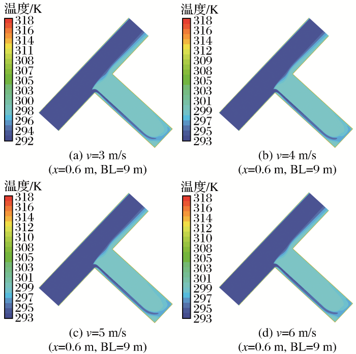
图13
温度分布随进气速度的变化
Fig.13
Change of temperature distribution with intake air speed
在不同进气速度下,巷道平均温度随着所在位置距掘进面距离的变化如图14(a)所示(其中BL=9 m,x=0.6 m)。在特定的流速下,巷道温度分布规律相同:随着所在位置距掘进面距离的增加,温度先快速上升后波动变化,在与进气道连接处下降;在距掘进面特定位置处,随着进气速度的增加温度越来越低,但温度降低的幅度变小。分析其原因如下:冷却气流由辅助通风设施引导流出后流向掘进面,冲击掘进面并在附近散开,因此掘进面附近通常会获得很低的温度;随着风速的增加,进入掘进巷道的风量也在增加,因此掘进巷道的温度随风速增加呈下降趋势。研究结果还显示,在掘进巷道和进气道的连接处温度并未下降到进气道中的空气温度(20 ℃),这是由于掘进巷道中的热量排出在进气道重新形成了一个温度高于20 ℃的区域。
图14
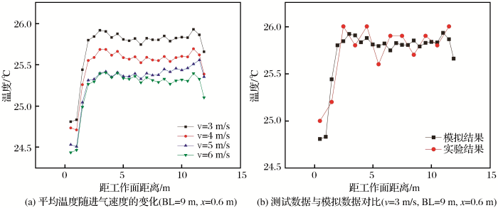
图14
进气速度模拟试验(a)及其与现场试验结果的对比(b)
Fig.14
Simulation experiment of intake air speed (a) and comparison between field test and simulation experiment (b)
为验证模拟结果的可靠性,在某矿山进行了现场测试(其中BL=9 m,x=0.6 m,v=3 m/s)。现场每隔1 m测定一次温度,结果如图14(b)所示,可以看出数值模拟结果与试验结果基本保持一致。由于测试选点和其他因素的影响,试验结果与模拟结果有一些误差,但二者整体发展趋势相似,结果符合预期。因此,数值模拟结果具有参考价值。
4 结论
建立了配备辅助通风设施的短距离高温巷道温度分布数值模型,通过数值模拟分析了不同辅助通风设施参数对短距离巷道的通风降温效果的影响。研究结果可为高温矿井局部通风降温设计提供参考,有助于提高井下作业的安全性和舒适性。
(1) 当没有使用辅助通风设施时,风速的增加不能显著提高进入巷道的风量。
(2) 通过引入辅助通风设施,巷道温度明显降低。对于增加辅助通风设施的全部案例,掘进面附近温度最低,随后温度快速升高,并在中间较长距离保持小幅波动状态,在进气道附近又快速下降。
(3) 辅助通风设施的长度及其与墙壁之间的距离会影响巷道的通风降温效果。随着长度的增加,降温效果先增强后减弱;增加辅助通风设施与墙壁之间的距离可以显著提高通风降温效果。
(4) 固定辅助通风设施的长度及其与墙壁之间的距离,提高进气道风速可以改善巷道内的降温效果。随着风速的增加,改善效果越来越不明显。
参考文献
A review on energy saving strategies in industrial sector
[J].
Case study: Energy savings for a deep-mine water reticulation system
[J].
深井掘进巷道热灾害预测模型研究
[D].
Study on Heat-calamity Forecast Model in Drivage Roadway of Deep Shaft
[D].
高温矿井温度场演化规律与降温技术研究
[D].
Study on Cooling Technology and Evolutional Law of Temperature Field in High Temperature Mine
[D].
Computational evaluation of thermal management strategies in an underground mine
[J].
高温矿井井巷热质交换理论及降温技术研究
[D].
The Study of Heat and Mass Transfer Theory and Cooling Technology in the Shaft and Runnel that in the High-Temperature Mine
[D].
Mine face ventilation: A comparison of CFD results against benchmark experiments for the CFD code validation
[J].
Numerical and experimental analysis of different ventilation systems in deep mines
[J].
The computational modeling of the ventilation flows within a rapid development drivage
[J].
The influence of ventilation arrangement on the mechanism of dust distribution in Woxi pithead
[J].
Auxiliary ventilation in mining roadways driven with roadheaders:Validated CFD modelling of dust behaviour
[J].
Dust dispersion and management in underground mining faces
[J].
Introduction and evaluation of a novel hybrid brattice for improved dust control in underground mining faces: A computational study
[J].
CFD modeling of ventilation ducts for improvement of air quality in closed mines
[J].
Some approaches to improve ventilation system in underground coal mines environment——A computational fluid dynamic study
[J].
深井高温热环境的数值评价
[J].
Numerical evaluation of thermal environment with high temperature in deep mine
[J].
掘进巷道风流热环境的数值模拟
[J].
Numerical simulation of the thermal environment at working face of diving airway
[J].
热害矿井气流与围岩热交换的数值模拟
[J].
Numerical simulation of heat exchange between air and surrounding rock in thermal hazard mine
[J].
CFD simulation of methane dispersion and innovative methane management in underground mining faces
[J].
Numerical simulation of methane distribution in development zones of underground coal mines equipped with auxiliary ventilation
[J].

 甘公网安备 62010202000672号